Saturday, 3 February 2018

Run Stand


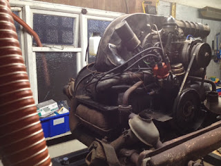
I've built a run stand so that I can test the engine before it goes back in.

I got a 12v gearbox end and welded up a frame to support it. The 'Dashboard' with the main power toggle, oil pressure light and coil switch I made from a spare wheel tub end I had lying around.

All of the toggles, lights and push to make switch are from Maplins.

Since I made the video above, I've also wired in the alternator as that's ultimately what I'll be replacing and testing.

The frame is 50mm square section and cost £40. The gearbox end was around £30. Then around £20 for switches, lights, wires and sundries. (I did replace the bushing in the gearbox).

Here are a few pictures I took whilst building the frame.


I ran the base to either side of the engine for sturdiness, and to allow me to jack up the engine from the centre to bolt it in.


The fuel tank was £7, it's for a petrol strimmer. I thought I'd put a filter in.


Here is the stylish mudguard / dashboard.


Keeps the wiring tidy and out of the way.

I got the heatproof (silicon I believe) hose for around £50


Tuesday, 22 March 2016

Fitting the sliding door

I used a middle sill repair section with the sliding track from Alan Schofield which I welded in as straight and level as possible from front to back.

However when it came to putting the sliding door back on, whilst there was smooth rolling for 4 fifths of the travel, the closing piece of track was too high causing the door to jam.

It seems as though the track needs to drop down as the door moves in at the final section to re-engage with the striker plate.

I had to cut a section of the repair section out and use it as a template to cut a new piece in. This was shaped with a gentle curve to get a drop of around 8mm as the door closes. 

The panel was tacked into place just enough to try the door out. 


Only 2 pictures to show for this but plenty of taking the door off and on!


Once the position was confirmed as being good, it was welded in properly and painted out ready for the outer sill.

Aaaagh! More holes under the passenger seat.

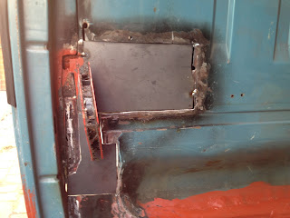
Having a clean around in the wheel tub with a screwdriver, I noticed a couple of significant holes under the passenger seat. As keen as I am on staying on track with only the repairs I was planning, these were quite large and had been patched over before, but were rotting out from underneath the patches.


By the time all of the rusty metal had been removed there was a significant hole!


The damage was centred on a step in the pressing, so I cut 3 sections to create a step, roughly similar to the original shape.

At the moment I want to make this water tight and to stop the seat dropping into the wheel tub, when I come this way again with more time, I might well make a more original looking repair.


Tuesday, 15 March 2016

Bulkhead and front wheel tub repair

The bulkhead and wheel tub had rotted out pretty much all around the central bulge pressing, and needed several sections cutting to shape to build it back out.

My aim was to get back to one solid skin and replace the 3x levels of patch from previous repairs.


Below the bulge I used an Alan Scholfield panel cut into 2 sections to fit between where the inner sill sticks out into the tub and the back of the tub above the chassis.


This was welded up against the bottom of the bulge and to the floor panel return in the cargo bay.


Previous (rotten) repair patch was removed and cut back to sound metal.


Patches were fabricated (I used 2mm steel here)


I seam welded the butt joint from both sides.


I decided to add a cosmetic strip on the left hand side to replace the original B pillar shape.
And then painted it all out with zinc primer.


Sunday, 6 March 2016

B pillar repair


The bottom of the B pillar had completely rotted out and needed fabricating from the cargo bay floor down. I started with a rear plate from the back of the pillar to the bottom of the inner sill and then cut and shaped sides, it was a fiddly repair that needed to be done one piece at a time to get the most space to weld into.

Here you can see the rear plate and a side plate in place.


And here it is from inside the front wheel tub.


I primed it as a went along to get as much paint over it as possible.


The outside of the B pillar needed cutting back higher to get to a knarly piece of rot behind the front wheel arch.


A B pillar skin repair panel from Alan Schofield was cut to finish the outside curve.


Then one or two smaller repair pieces were cut to get the outside curve correct.


Then the wheel tub side of the pillar was repaired ensuring that the pillar had it's own structural shape behind the (good) front wheel arch.


The repair pieces were ground into shape to the B pillar curve.


The repair sections were seam welded around.


And re-primed.


Friday, 4 March 2016

Positioning and fitting the front outrigger


Time to fit that front outrigger! I clamped this together time and time again, right through the process of positioning and welding in the sills. So I was pretty sure all of the positioning was good.

I used a jack to hold the position and made sure that the top hat section would fit in between the outrigger and the cargo bay floor.

There was a small amount of adjustment to the flaps on the outrigger to get it to sit as neatly as possible against the chassis rail.

You can see the outrigger, top hat section etc in place below.


Here is the front outrigger in place from behind, you can see how it sits under the inner sill.

I also test fitted the rear outriggers to make sure I wasn't committing myself to something that would later prove problematic.


Just for a laugh I thought I'd position the patches for the front wheel tub. Not ready to fit them yet, but it was a heart warming sight.


Removing the inner sill


The inner sill wraps behind the middle sill and to remove it, I had to drill out the spot welds from the cargo bay floor. This had been repaired previously and it was difficult to judge which welds held the sill and which didn't.

When drilling out these welds, it's important to double check you are removing those that hold the inner sill as there is a row that attach the door runner channel, and you do not want to remove that. As refitting the sliding door would be a nightmare.


When the inner sill went into place I used the holes created drilling out the original spot welds to weld the new sill into place, and clamped it up to the middle sill at the front to stop them splaying apart where they meet.


Below you can see the inner sill welded to the end of the middle sill, this L shape will show through into the wheel tub when the tub skin is back in place. The observant among you will notice that the base of the B pillar to the right hand side of this picture is conspicuous by it's absence.  That's another one for the list.